SciFig

Free P&ID Diagram Generator

Connect the equipment and keep its tags readable. Distinguish pipes from signals, follow the connection key and download a diagram you can reopen.

Describe what you need in the box above.

Start with up to 150 free credits|No credit card required

Get up to 350 free credits on day one when you join through an invite.

3 figure engines · 500+ templatesEvery label editable · 60+ color schemesEditable PPTX · Layered SVG · 8K PNG / JPG

Draw piping and instrument connections

Choose equipment symbols, enter unique tags and connect the equipment with pipe or signal lines. Download the figure or save its settings for later edits.

Use two to eight equipment items and one to twelve connections. Solid lines represent pipes and dashed lines represent signals. The connection key lists each ID and its endpoints.

Equipment

Equipment 1
Equipment 2
Equipment 3

Connections

Connections 1
Connections 2

Free P&ID Diagram Generator— templates & examples

Updated

Equipment tags, pipes and signals

Free P&ID Diagram Generator

Keep the equipment, connection lines and descriptive key together in an editable diagram example.

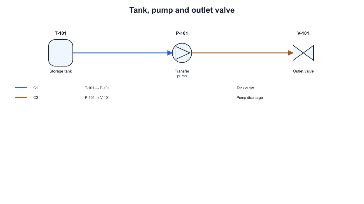
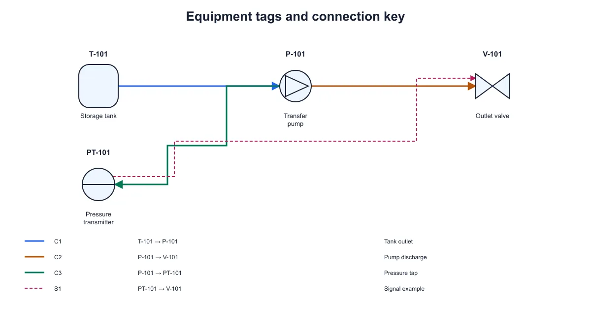
SciFig’s PID diagram generator turns equipment tags and explicit connections into a piping and instrumentation diagram. Choose vessel, pump, valve and instrument symbols, then select the source and destination of each connection. Solid pipes and dashed signal lines remain distinct, with a connection key listing their IDs, endpoints and descriptions. Download SVG or PNG and save the settings to revise the same diagram later.

Tank, pump and valve linked by two solid process pipes with a connection key below
  • Name equipment and unique tags
  • Connect equipment with pipes or signals
  • Read IDs and endpoints in the connection key
  • Download SVG, PNG and saved settings

P&ID Diagram Generator Features

Make the equipment and its connections explicit in a diagram you can revise.

Choose equipment and give it a unique tag

Add vessel, pump, valve and instrument symbols, then enter an equipment ID, a tag and a short description. Tags help readers match the symbols to the terminology used in your example. SciFig’s PID diagram generator keeps equipment identities separate from their descriptive labels so you can update the wording while retaining the connection references.

  • Choose the available equipment symbols
  • Enter a unique equipment tag
  • Keep descriptions beside the symbols
Try this in SciFig

Distinguish process pipes from signals

Use the P&ID diagram generator to select the source and destination equipment for each connection, then choose process pipe or instrument signal. The preview draws pipes as solid lines and signals as dashed lines. Direction arrows show the entered source-to-destination relationship, helping readers distinguish material-path examples from instrument connections.

  • Select both equipment endpoints
  • Use solid pipes and dashed signals
  • Follow the entered connection direction
Try this in SciFig

Read connection details in a separate key

The key below the equipment lists every connection ID, its source and destination tags and its description. A matching line sample helps readers associate each row with the diagram. Keeping these details together gives you room for readable labels without placing every description over the routed connection lines.

  • Match each connection with its ID
  • Read source and destination tags
  • Keep descriptions clear of routed lines
Try this in SciFig

Download a figure and retain its inputs

Export SVG when you want a vector file for further editing, or PNG when the diagram belongs in a slide, worksheet or document. Save JSON settings to retain the equipment types, IDs, tags and connections. Reopen them in the P&ID diagram generator when you need another version of the same example.

  • Export SVG or PNG
  • Save equipment and connection settings
  • Reopen the same example for revisions
Try this in SciFig

How to Create a Piping and Instrumentation Diagram

Define the equipment, connect it and inspect the key before exporting.

  1. Add the equipment and tags

    Choose the symbols needed for your example and enter a unique equipment ID and tag for each item. Add a short description so readers can recognize the role of the equipment alongside its symbol.

  2. Enter the pipe and signal connections

    Give each connection its own ID, select the source and destination equipment and choose pipe or signal. Add a description when it helps explain the connection in your example.

  3. Check the diagram and connection key

    Follow the solid and dashed lines, check their direction arrows and read the corresponding rows in the key. Confirm that the tags and descriptions match the equipment and connections you intended to show.

  4. Download and save the settings

    Export SVG or PNG for your notes, presentation or document. Save the JSON settings beside the figure so you can reopen the equipment tags, connection types and descriptions when the example changes.

P&ID Examples for Explanations and Documents

Show equipment relationships with readable tags and an explicit connection key.

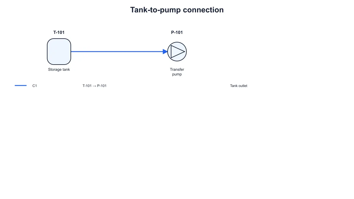
Tagged storage tank connected to a transfer pump by one solid process pipe

Explain a tank-to-pump path

Start with a vessel and pump to show a simple material path. Give the equipment recognizable tags and describe the connecting pipe in the key. This small example helps readers relate the source and destination fields to the line in the diagram.

Explore this example
Tank, pump and valve linked by two solid process pipes with a connection key below

Add a valve to a process example

Use a tank, pump and valve to describe the equipment order in a transfer example. Keep the tags distinct and label the pipe connections in the key. Export the piping and instrumentation diagram for a handout or a discussion beside the process notes.

Explore this example
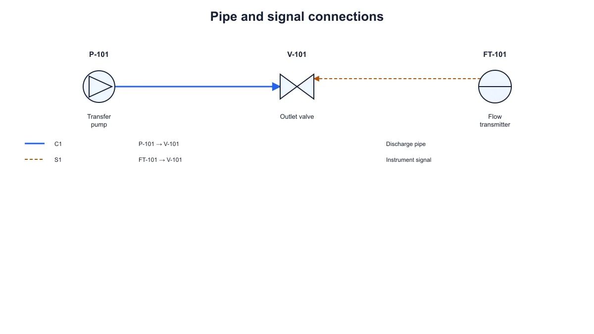
Pump and valve joined by a solid pipe with a dashed signal from a tagged instrument

Compare pipe and signal lines

Place an instrument beside the process equipment and add a signal connection. The dashed line distinguishes it from the solid process pipe, while the key identifies both endpoints. Use the exported figure when explaining how these connection types differ in a simplified P&ID example.

Explore this example
Four tagged equipment symbols with solid pipes, a dashed signal and a four-row connection key

Connect tags with written descriptions

Give each equipment item a tag and add descriptions to the connections. The key keeps the IDs, endpoint tags and text together below the drawing. Use this view beside a written explanation that refers to particular equipment or connection identifiers.

Explore this example
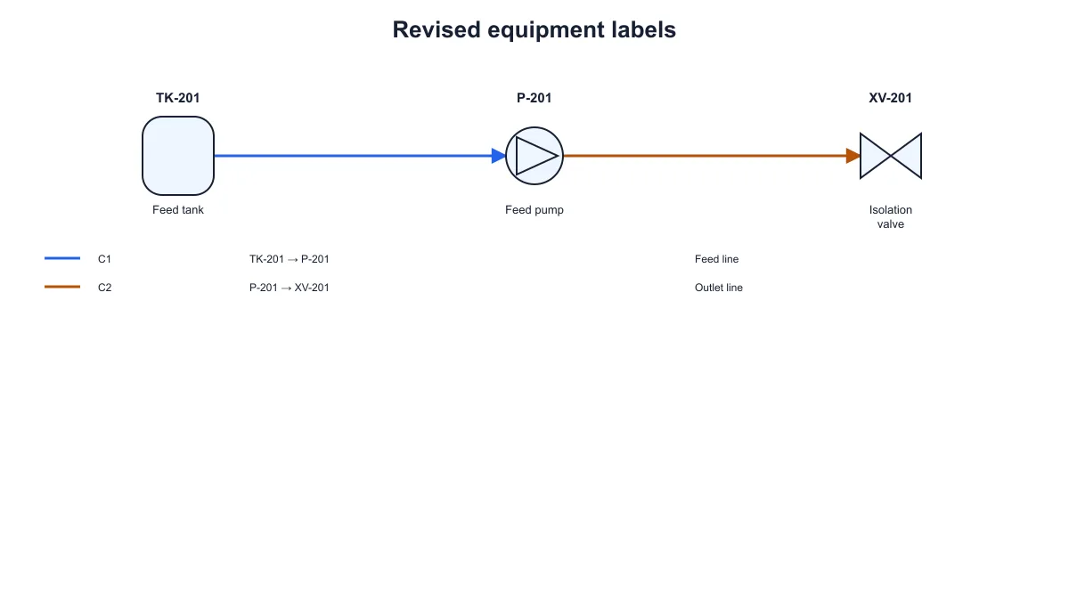
Feed tank, feed pump and isolation valve with revised tags and labeled connection rows

Prepare related versions of one diagram

Save the settings after you create an example, then reopen them to change the equipment tags or descriptions. The existing connections remain tied to their equipment IDs. Export a revised figure when you need another version for a worksheet, slide or document.

Explore this example
Tank, pump and valve linked by two solid process pipes with a connection key below

Choose between a P&ID and a workflow

Use equipment tags and pipe or signal connections when those details are central to your explanation. For a sequence of activities, decisions and handoffs, continue to SciFig’s workflow diagram generator. Choose the structure that matches the relationship you want the reader to follow.

Explore this example
How Researchers Use SciFig

I needed a small tank and pump example with tags that matched the notes for a tutorial. The PID diagram generator let me enter the equipment and describe the connecting pipe in the key. I exported the figure and kept the settings with the worksheet so I could revise the labels later.
Charlotte M.

Chemical engineering teaching assistant, University of Leeds

Free tools

A tool for every scientific figure

110 focused generators for the scientific figure you need — each opens in the right workspace with a matching example.

P&ID Diagram Questions

1.

2.

3.

4.

5.

6.

Call to action background

Equipment tags, pipes and signals

Make equipment connections easy to follow

Create a P&ID diagram

Free to start · No credit card required · Built for researchers