
Circuit Diagram Maker
Generate accurate circuit diagrams with labeled schematic symbols for research papers, lab reports, and technical publications.
Figure prompt
Describe the figure you want to create
Not sure where to start? Use Example.
Start with 100 free credits|No credit card required
Get up to 300 free credits on day one when you join through an invite.
Reviewed by SciFig TeamUpdated
Circuit Diagram Maker— templates & examples
Everything you need to create a publication-ready circuit diagram
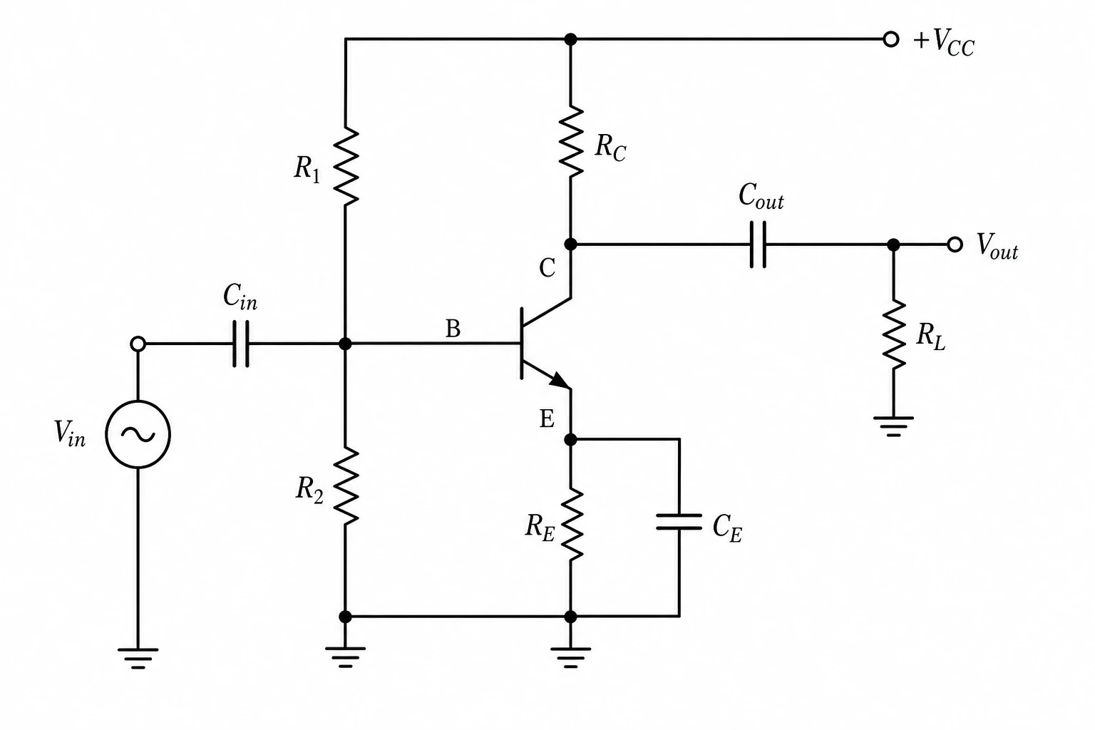
Accurate schematic symbols from plain-language descriptions
Describe your circuit in everyday language — component names, values, and how they connect — and SciFig's circuit diagram maker AI renders the correct schematic symbols automatically. Resistors, capacitors, transistors, voltage sources, and ground references all appear with standard IEC/IEEE notation, so your circuit diagram meets the figure conventions required by journals, lab reports, and conference papers. No manual symbol libraries or drawing software needed.
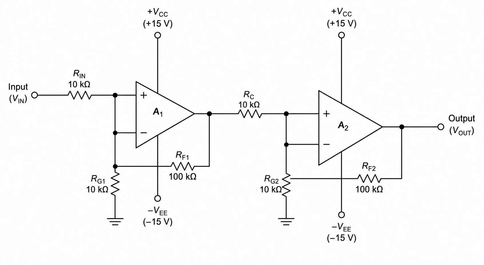
Full wiring diagram and schematic support
Whether you need a logical schematic diagram for a publication or a more layout-oriented wiring diagram maker output for a lab manual, SciFig adapts to your description. Specify signal paths, power rails, and component placement in your prompt, and the generated circuit diagram reflects the structure you need. Every figure stays fully editable — adjust values, add labels, recolor nodes, and export at the resolution your target journal requires.
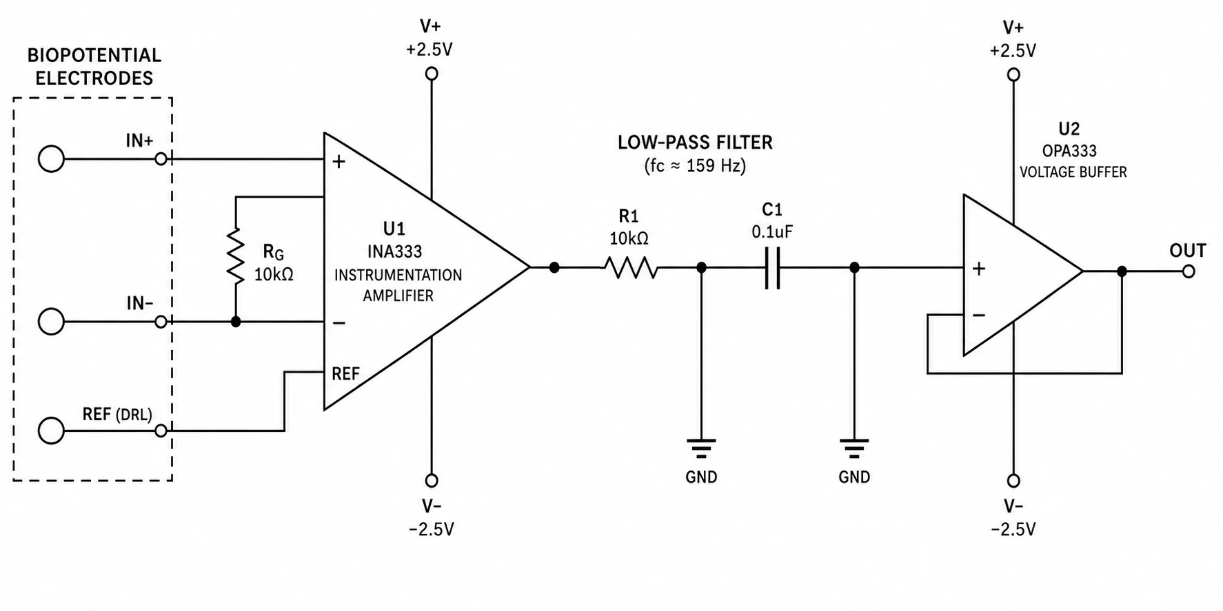
Built for research figures and technical documentation
Circuit diagrams generated by SciFig are designed to the visual standard that physics and engineering reviewers expect: clean line weights, consistent symbol sizing, readable component labels, and a white background suitable for print and digital publication. Export your schematic diagram maker output for inclusion in IEEE papers, Nature Electronics, thesis appendices, or grant technical narratives — without reformatting.
What is a circuit diagram?
A circuit diagram represents an electrical circuit using standard schematic symbols — resistors, capacitors, transistors, voltage sources — to show components and conducting paths, and is the required figure format in electronics research and physics papers. With SciFig's circuit diagram maker you describe your circuit in plain language and receive a clean, labeled schematic you can edit, annotate, and export at the resolution your target journal requires.
Why circuit diagrams matter in research
- Allow readers and reviewers to understand and replicate your experimental setup
- Provide a compact, unambiguous record of circuit function independent of physical hardware
- Are required by IEEE, AIP, and most engineering journals as a standard figure type
- Make it easy to identify signal paths, feedback loops, and component interactions
- Enable peer verification of measurement and characterization circuits
- Serve as the authoritative figure in patents, grants, and technical reports
Key elements of a circuit diagram
- Resistors — limit current flow, shown as rectangles (IEC) or zigzag lines (IEEE/ANSI)
- Capacitors — store charge, shown as two parallel plates with optional polarity marker
- Transistors — amplify or switch signals, drawn as BJT or MOSFET schematic symbols
- Voltage and current sources — DC batteries or AC circles labeled with magnitude and frequency
- Ground references — indicate the zero-volt reference node, essential for signal tracing
- Wire connections — straight lines; junctions marked with filled dots to avoid ambiguity
Where circuit diagrams are used
- Electronics and electrical engineering research papers and journal articles
- Physics experimental setup documentation (amplifier, sensor, and detector circuits)
- Biomedical engineering device and instrumentation schematics
- Materials science characterization circuit figures (four-probe, lock-in, impedance setups)
- Thesis and dissertation appendices describing custom-built measurement hardware
- Patent applications, grant proposals, and technical product documentation
How to make a circuit diagram
Describe your circuit diagram
Tell SciFig what to draw in plain language — no design tools required.
Generate with SciFig
Get a clean, publication-ready figure that matches your description in seconds.
Edit & export
Vectorize it into editable SVG, relabel everything, and export for your paper, poster, or slides.
Circuit Diagram Maker — Frequently Asked Questions
Common questions about Circuit Diagram Maker.
More tools
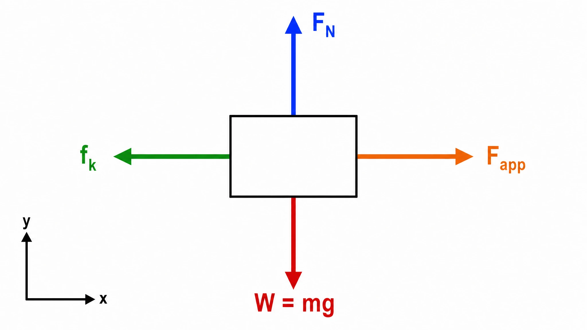
Free Body Diagram Generator
Create accurate, publication-ready free body diagrams with labeled force vectors for weight, normal force, friction, and tension in seconds.

Graphical Abstract Maker
Generate a publication-ready graphical abstract — a single-panel visual summary that captures your study's methods, key finding, and result with clear icons and flow arrows.
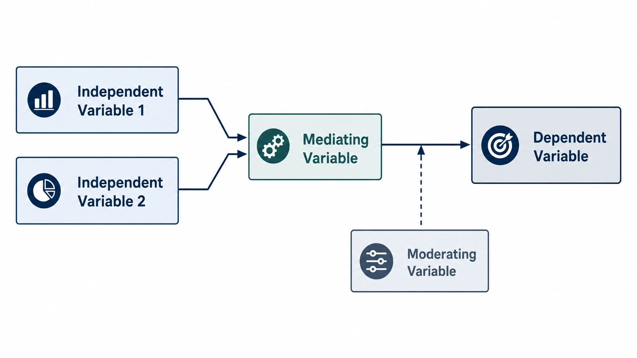
Conceptual Framework Generator
Create professional conceptual framework diagrams showing variable relationships, hypotheses, and theoretical models for your research.
Home
Free AI Scientific Figure Generator and Figure Maker — Create Research Figures, Images, Illustrations and Diagrams
Text-to-Figure
Generate a figure from a plain-language description
Models
Default to GPT Image 2 for journal papers; switch to Nano Banana Pro for slides and posters; pick Nano Banana 2 for routine figure work
Tutorials
Seven short walkthroughs of the AI scientific figure generator
Blog
Tutorials, tool comparisons, and publication tips for researchers.
Inspiration
Explore publication-ready scientific figure examples, copy the prompts, and use them as starting points for your own work.

Ready to publish?
Make your own circuit diagram in minutes.
Start for freeFree to start · No credit card required · Built for researchers