
Action Potential Diagram Labeled 02
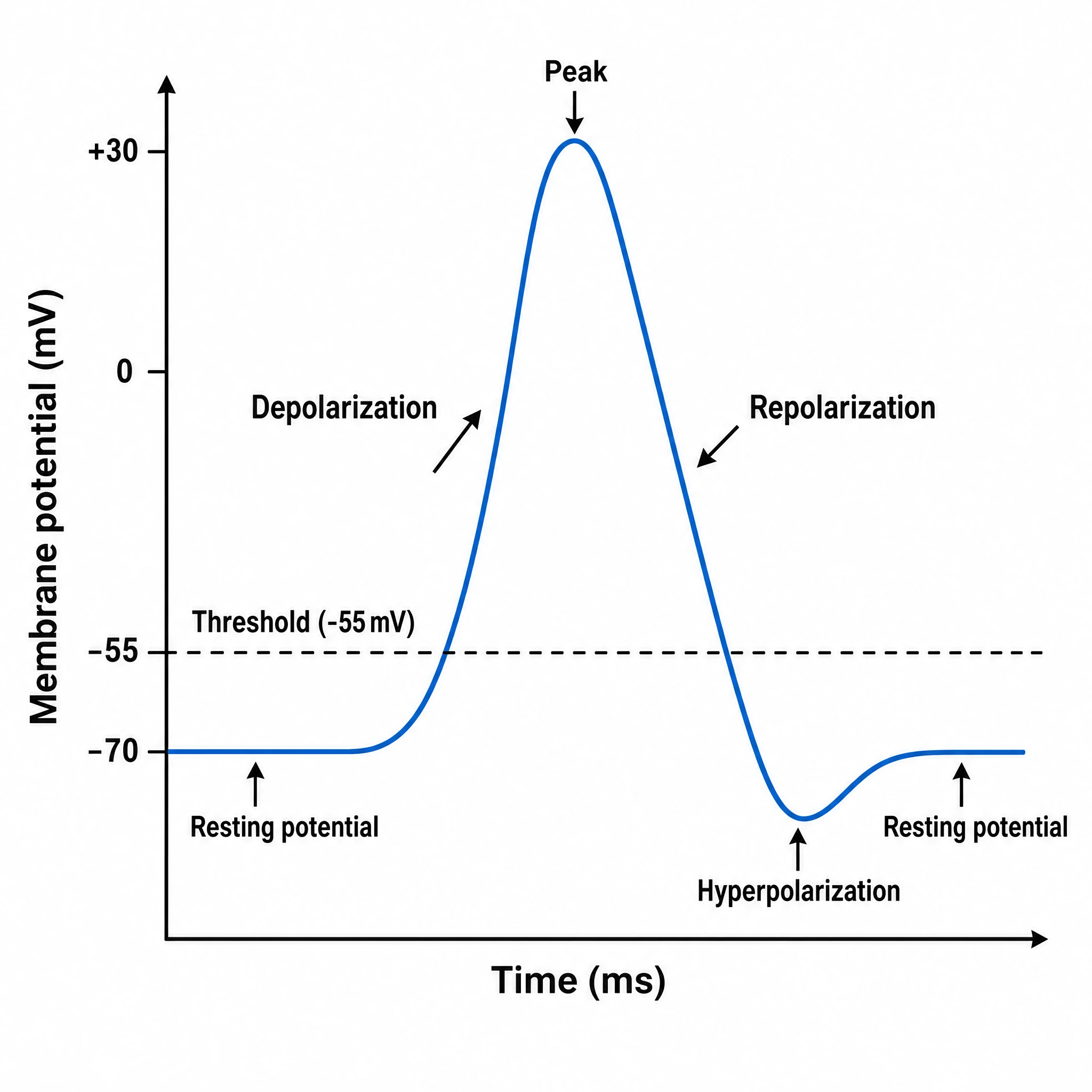
A labeled action potential graph plotting membrane potential over time, with threshold, depolarization, the +30 mV peak, repolarization, and hyperpolarization marked.
Updated

Start with up to 150 free credits|No credit card required
Get up to 350 free credits on day one when you join through an invite.
What is Action Potential Diagram Labeled 02?
A labeled action potential graph is a diagram that plots a neuron's membrane potential over time as it fires, with each phase named. It starts near the -70 mV resting potential, rises to the threshold, depolarizes sharply to a peak around +30 mV, repolarizes back down, dips into hyperpolarization, and returns to rest. With SciFig you describe the trace in plain language and generate a clean, editable action potential graph, ready to relabel and export.
Why the trace is drawn from the electrophysiology, not from memory
- Every phase name on the curve maps to a specific ionic event, so a trace with the wrong shape teaches the wrong mechanism — the rising phase must be steeper than the falling phase because voltage-gated Na⁺ conductance activates far faster than K⁺ conductance.
- The axis values are the content. A trace without millivolts on the y-axis and milliseconds on the x-axis is decoration; with them it is a quantitative claim a reader can check against their own recordings.
- The undershoot is diagnostic and routinely omitted. Delayed-rectifier K⁺ channels close slowly, so the membrane transiently sits below rest — a curve that returns straight to baseline has drawn away the mechanism.
- The all-or-none property depends on threshold being drawn as a distinct level with subthreshold depolarisations failing at it; a figure showing only the successful spike cannot make that argument.
- Cell type matters and is usually left implicit. A squid or mammalian axonal spike lasts ~1–2 ms; a cardiac ventricular action potential has a plateau and lasts 200–400 ms. Reusing one shape for the other is a substantive error.
Phases and features to label
- Resting membrane potential at approximately −70 mV (neuronal), set by K⁺ leak conductance and the Na⁺/K⁺-ATPase, drawn as a dashed baseline that persists across the whole x-axis.
- Threshold at roughly −55 mV, marked as a horizontal dashed line, with at least one failed subthreshold depolarisation shown beneath it to make the all-or-none point.
- Rising phase / depolarisation: rapid Na⁺ influx through voltage-gated Na⁺ channels in regenerative positive feedback, driving the membrane toward E_Na (≈ +60 mV).
- Peak at about +30 mV — note that it undershoots E_Na because Na⁺ channels begin inactivating and K⁺ channels begin opening before equilibrium is reached.
- Falling phase / repolarisation: Na⁺ channel inactivation gates close while delayed-rectifier K⁺ channels open, so net K⁺ efflux returns the membrane toward rest.
- Hyperpolarising afterpotential (undershoot) below −70 mV, approaching E_K (≈ −90 mV), caused by slow K⁺ channel closure.
- Refractory periods drawn as bars beneath the trace: the absolute refractory period (Na⁺ channels inactivated, no stimulus can fire a second spike) and the relative refractory period (recovering channels plus residual K⁺ conductance, so a stronger-than-normal stimulus is required).
Where the labeled trace is used
- Neuroscience teaching figures and lecture slides on excitability, conduction, and the Hodgkin–Huxley formulation.
- Pharmacology figures showing channel-blocker effects — tetrodotoxin abolishing the upstroke, TEA broadening repolarisation, local anaesthetics on use-dependent block.
- Channelopathy and disease figures: gain-of-function Na⁺ channel mutations in epilepsy, loss-of-function in periodic paralysis, and long-QT variants in the cardiac analogue.
- Patch-clamp methods panels, where the schematic trace is placed alongside real recordings to orient the reader before showing data.
- Comparative panels contrasting neuronal, cardiac (phases 0–4 with a Ca²⁺-mediated plateau), and skeletal muscle waveforms on a shared time axis.
- Computational neuroscience figures where a modelled spike is compared to the canonical shape, and the conductance traces (g_Na, g_K) are stacked below.
Action Potential Diagram Labeled 02— templates & examples
How to make Action Potential Diagram Labeled 02
Describe your figure
Tell SciFig what to draw in plain language — no design tools required.
Generate with SciFig
Get a clean, publication-ready figure that matches your description in seconds.
Edit & export
Vectorize it into editable SVG, relabel everything, and export for your paper, poster, or slides.
Related searches
- labeled action potential graph
- action potential diagram
- action potential graph
- membrane potential graph
- depolarization chart
- repolarization on graph
- action potential phases diagram
- threshold potential graph
- neuron membrane potential plot
- graph action potential
Make figures for
Related pages
Neuroscience Icons
Browse more Neuroscience icons in SciFig's library.
All Icons
Browse every icon page in SciFig's library.
AI Scientific Image Generator
Generate research figures from text
Graphical Abstract Maker
Summarize your study in one panel
Text to Diagram Generator
Turn text into a diagram
Scientific Poster Generator
Design a conference research poster
Frequently Asked Questions
Common questions about Action Potential Diagram Labeled 02.

Ready to publish?
Make your own Action Potential Diagram Labeled 02 in minutes.
Start for freeFree to start · No credit card required · Built for researchers